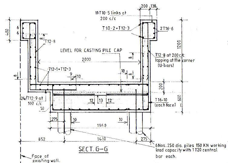
Here is a hand drawing of a typical lift pit associated with this scheme.
This profile has been used so as to miss the foundations to the existing lift shaft structure.
The draughtsman did not bother to indicate the existing foundations on this section, but they are there.
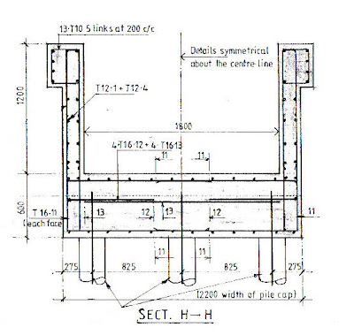 With nothing in the way, the section in the other direction is symmetrical about the centre line of the lift shaft.
Lots of drainage and electric cables and gas services pipes were found on site so a few dimensional modifications to the Tender Drawing extract details shown above have been made, however this gives you a basic idea of what It is I’m trying to model.
At some stage in the future I want to add the reinforcement details.

Here is a screen dump of my first floor plan.
I altered the scale from 1:100 to 1:50 to reduce the size of the grid bubbles so they became a little smaller on the screen and more in keeping with the size of the detail.
Whilst taking this screen dump I noticed that the Grid Line Bubble (A) did not line up with the others, so I fixed it, now they all line up.
The bending / moving of the Grid Line to move the Bubbles apart was shown in a CADClip so I followed the example I had seen.
Having seen Daryl take sections in his CADclip videos, I then decided to cut a section between grid lines 1 and 2 looking up the page. The section is shown below

To begin with the columns looked short and stubby. Until I realised that I had to drag down the view area so that I could see the Ground Level. In fact I dragged the box down further so that I could see the pit and top of the pile foundations that I was about to model.
I selected the Ground Level Structural Wall then Basics and Structural Wall
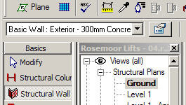
Looking at the walls available, the best fit I could find was Basic Wall: Exterior – 300mm Concrete.
The wall I wish to detail is only 200mm thick, so I clicked on the Element Properties button
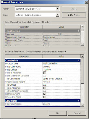
This gave me the Element Properties dialogue shown above
I then selected Edit / New… to get the Type Properties dialogue below
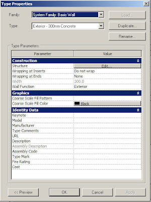 Hitting the Duplicate Button
I named the Type as Exterior – 200mm Concrete and hit the Value Edit… button to alter the width from 300 to 200
I forgot to alter the Base Offset from -4000 to -1200, so once drawn and viewed in 3D, I had to select the walls, then right clicked, Properties and altered the Base Offset dimension.

Now at least my structure is starting to look as if something might be holding it up
Looking at this view there are a couple of things that went through my mind:-
1) The tops of the concrete columns Top Offset needs to moved down so that the columns protrude into the concrete slab by 50mm – Ummm need to check that this actually will show in a section.
2) This then also starts me thinking about showing or modelling the kicker to the walls….. Ummmm something else to look at.
3) Must recall how to turn off the structural framing lines in the view – seen it in one of the CADClips but can’t recall which one
4) I have drawn the steel columns as having a joint at each floor level. Actually they are much longer (just over two floors high) and have connections above the floor level not in line with it. Is it worth tweaking? Can I model the connection details? How and would it affect the design model?
5) At the moment the 1st floor slab is the wrong material and the wrong profile, as it has a sloping bottom. I know this, but wanted to get something drawn and will come back to this later.

Here is what the profile of the slab should look like looking at Flank Elevation.
6) I also will need to tweak the bottom of the steel columns and add baseplates
So I feel like I’m climbing this big knowledge tree. I’m kind of getting up the trunk and can now see all these main branches with many other branches off them and twigs coming off
Next time…..
The base slab, pile cap, and piles then adding the beam thickening to the top of the walls…


No comments:
Post a Comment